Tripod mountable stereoscopic 3D Camera that transmits a stereoscopic video stream over HTTP to a stereoscopic viewer like Google Cardboard
Stereoscopic 3D images/video attempt to replicate what we see with our own eyes. Your eyes are approximately 2.5 inches or about 6cm (60mm) apart (also called interocular distance). As a result, each eye sees the image from slightly different perspectives and angles. The brain combines these two images into a seamless image and also uses the information to gauge distance and depth. This is also called binocular vision.
We can replicate this with a 3D Stereoscopic Camera, by having two cameras that are separated by roughly the interocular distance. These two images (left image and right image) are then presented individually to each eye using a stereoscopic viewer like Google Cardboard. The brain then combines these images and processes the subtle differences in perspective and angles to create depth perception, or a 3D image!
We'll build a stereoscopic 3D camera using two Raspberry Pi Zeros and two Pi Camera 2s (since each Raspberry Pi can only support one camera). In order to make a usable camera, we also need a proper enclosure.
Here we use the ProtoStax Enclosure for Raspberry Pi Zero, which can accommodate two Raspberry Pi Zeros (what a coincidence! 😊). We also use the ProtoStax Stereoscopic 3D Camera Kit for Raspberry Pi Camera - 60mm Stereo Base which allows you to mount two Pi Camera 2 situated, you guessed it 60mm apart – our interocular distance (also called interaxial distance or stereo base when referring to camera setups)!
We'll use some Python to stream the camera output into a composite left-eye/right-eye browser-based video stream. You can then open this stereo video stream up on a browser on your mobile phone and place it in a stereoscopic viewer like Google Cardboard, and voilà! - we have our 3D stereoscopic Streaming Camera and Viewer!
You can also make the 3D Streaming Camera more portable by using an RPi UPSPack V3 to add a battery backup, so you are not tethered by wires and can move around.
Now you can give a 3D house tour to your Nana or Abuelo without having to make them climb the stairs or leave the comfort of their chair, as you go and operate the camera for them to view remotely!
Or have silly 3D games where you show your friends or family themselves as they view the world you present through the Google Cardboard - turn the camera and point it at them, and watch their reaction as they see themselves in 3D! Quite trippy!
Disclaimer - People with motion sickness can get a bit queasy when viewing VR headsets or stereoscopic cameras. If you start to feel queasy, just ease off the stereoscopic camera viewing! 😊
Ok, let's get started!
Item |
Quantity |
Raspberry Pi Zero W (with headers) | 2 |
Raspberry Pi Camera Module 2 | 2 |
ProtoStax Enclosure for Raspberry Pi Zero | 1 |
ProtoStax Stereoscopic 3D Camera Kit for Raspberry Pi Camera - 60mm Stereo Base (shown with long-side and short-side tripod mounts) | 1 |
Female-female jumper wires | 2 |
Google Cardboard (or similar) | 1 |
Optional items: |
(for a more portable setup) |
ProtoStax Enclosure for RPI UPSPack Standard V3 | 1 |
RPI UPSPack Standard V3 | 1 |
Tools: |
|
Screwdriver - Phillips #1 | |
Screwdriver - Slotted 2.0mm | |
Lens Adjustment Tool for Raspberry Pi Camera |
If you are starting afresh, you need to first configure the SD cards for your Raspberry Pi Zeros with the Raspberry Pi OS. The Raspberry Pi Imager tool allows you to do some configurations ahead of time when you create your boot image.
Firstly, note that we use Raspberry Pi OS Buster, which is not the latest version (called Bullseye at the time of this writing). Bullseye has made some fundamental changes to camera support. New Raspberry Pi OS releases will no longer support the familiar raspicam apps and Picamera Python library ). The new libcamera apps don't have Python support yet.
As a result, we've decided to stick with Raspberry Pi OS Buster and use the Python picamera library. There is a new picamera2 library in the works for Buster which will add Python support.
Secondly, we assume that the two Raspberry Pi Zeros are called leftcam.local and rightcam.local respectively in our sample code. If you're starting afresh, you may as well name the two Raspberry Pis appropriately when creating the SD card images.
If you already have configured Raspberry Pi Zeros, you can simply update the code with the names corresponding to your Raspberry Pi Zeros.
Since we'll be using the Raspberry Pi Zeros in a headless setup (not connected to a monitor or TV), you'll need to enable SSH on them.
To make the wiring simpler, we'll have the two Raspberry Pi Zeroes share power, so the setup only needs one power cord (or battery pack hookup in the case of the portable setup). To do that, we connect the 5V and GND lines of the two Raspberry Pi Zeroes via the GPIO headers (we connect pins 2 and 6 in our setup - see https://pinout.xyz/ for more details). Make sure to double- and triple-check the connections as you risk damaging the Pis if the wiring is incorrect.
Additionally, make sure you use a sufficiently powerful power supply that can provide the power needed for both Raspberry Pi Zeroes - the official Raspberry Pi power supply for the 3B+ (with the micro USB) puts out about 2.5A and should be sufficient for the two Zeros.
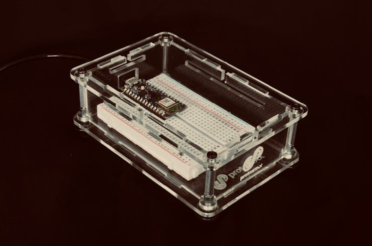
Start by mounting the two Pi Zero Ws on the ProtoStax Enclosure for Raspberry Pi Zero and the connect the "power rails" via jumper wires, as shown.
Next up, mount the Raspberry Pi Camera 2s to the Top Plate of the ProtoStax Stereoscopic 3D Camera Kit for Raspberry Pi Camera.
Connect the camera wires to the Pi Zeroes. Alternately, you can connect the cameras to the Pi Zeroes before you mount the cameras to the Top Plate! Whatever you find easier!
Add the side walls (including the two Tripod Mount side walls from the ProtoStax Stereoscopic 3D Camera Kit for Raspberry Pi Camera), and close everything up.
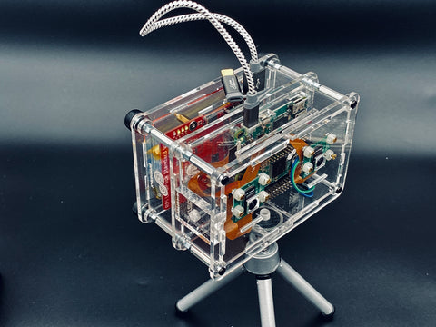
Here is the final completed stereo camera setup, with an attached Tripod mount adapter plate (this will totally depend on the type of tripod you have!).
Before we can use the cameras, we need to enable the camera interface on the Raspberry Pi Configuration. We can do this via the command-line utility raspi-config , on each of the Raspberry Pis!
pi@rightcam:~ $ sudo raspi-config
You can download the software from GitHub. Alternately, you can install it using git
sudo apt install git
Install on each your two Raspberry Pi Zeros. The program assumes that the two Raspberry Pi Zero Ws are named leftcam.local and rightcam.local. Either name the Raspberry Pi Zero Ws as above, or note their actual names to update in the program
git clone https://github.com/protostax/ProtoStax_StereoscopicCameraPi.git
cd ProtoStax_StereoscopicCameraPi
python3 stream.py
Each program will expose an MJPG video stream of the local camera via a simple webserver of the local video as
http://leftcam.local:8000/stream.mjpg and http://rightcam.local:8000/stream.mjpg
The program also has a home page (index.html) that will expose both video streams as a stereoscopic image (side-by-side), as
http://leftcam.local:8000/ or http://rightcam.local:8000/
(you can access the stereoscopic stream from either url)
You can open the link on your mobile phone browser and place the phone in a 3D stereoscopic viewer like Google Cardboard (or similar viewer) to get a 3D stereoscopic streaming camera on your viewer.
The viewer can thus see everything in 3D. The camera operator can move around to give the viewer a 3D tour from the comfort of their couch!
For optimal performance, you can focus the lens of the Raspberry Pi Camera 2 for a crisper image. You can use Lens Adjustment Tool for Raspberry Pi Camera to easily adjust the focus.
For best streaming performance, make sure you don't have too many other programs or services running on your Raspberry Pi Zeros. If you're starting off with a clean slate with your SD card images, this should not be a problem. However, if you're starting with existing Raspberry Pis with already configured SD cards, do ensure that you've stopped and disabled extra services, so streaming performance is not affected.
When you open the stereoscopic streaming link on the browser on your mobile phone, it is best if you hide the toolbar, so extraneous elements are minimized in the viewer. You will need to adjust the phone laterally in the viewer so that the image appears as a single smooth one that appears 3D (and there are no blurry artifacts).
Vertically Stack your setup with a ProtoStax Enclosure for RPI UPSPack Standard V3 containing an RPi UPSPack Standard V3 for a portable setup with backup power, so the camera operator is not bound by power cables. When the battery is low, the camera setup can be plugged back in to provide power and also recharge the battery.
The code for this is based on the Picamera library's Advanced Recipe for Web Streaming of video, which starts recording the camera's video stream to a buffer and then feeds the frames via a http request handler. The web server is started on port 8000. You can see each individual mjpg stream using leftcam.local:8000/stream.mjpg or rightcam.local:8000/stream.mjpg url.
This simple web server will additionally configure both left and right mjpg streams into a single page with split views using some HTML and CSS and provides that in response to the request for the home page (leftcam.local:8000/ or rightcam.local:8000/) or the index.html page (leftcam.local:8000/index.html or rightcam.local:8000/index.html). Thus opening up the home page of either leftcam or rightcam will provide a stereoscopic video stream.
Here is the HTML and CSS used to format the page:
<html>
<head>
<style>
.viewfinder {
display: flex;
flex-wrap: wrap;
}
.viewfinder-item {
height: 50%;
width: 50%;
object-fit: contain;
}
</style>
</head>
<body>
<div class="viewfinder">
<img class="viewfinder-item" src="http://leftcam.local:8000/stream.mjpg" />
<img class="viewfinder-item" src="http://rightcam.local:8000/stream.mjpg" />
</div>
</body>
</html>
In order for the code to run automatically on bootup, you will want to run it as a service. The GitHub page's README has instructions on how to do that, including the configuration file for the service.
As always, I like to end by talking about how you can take this project forward with your own additions! Once you get comfortable playing around with the code sample and understanding the code, it is always nice to try to extend your learning by doing more. Here are some suggestions:
Can you think of other ways to extend this project? Share it with us in the comments below! 😊 Also do share photos/videos of your creation on your social media platform of choice - just tag it #ProtoStax and tag us @protostax so we can find you!
Happy Making! 😊
Sridhar
]]>
The Waveshare RPi IR-CUT Camera is different in that it has an embedded removable IR-CUT (or IR Cutoff) filter. This means that the IR filter can be turned on or off as desired electronically, allowing you to take both day- and night-time photography with it.
For daytime shots, this means that your images will not have the color distortion that we saw with the Pi NoIR Camera, while still having the ability to disable the IR filter and take night-vision photography/videography. Additionally, it comes with two attachable IR LED lights, which means that it has its own IR light source (of course, you can always embellish it with outside IR light sources).
The Day/Night Mode on this camera can be toggled in two ways:
The IR-CUT Camera is a 5 MP camera as opposed to the 8 MP of the Pi NoIR 2 ( the original Pi NoIR is also a 5MP camera). However, unlike the Pi Camera, it has easily adjustable focus by rotating the camera lens till you get your desired focus. It also comes in two flavors: IR-CUT and IR-CUT (B) that have different lenses.
ProtoStax already supports the Raspberry Pi Camera Module/NoIR (both V1 and V2) with its ProtoStax Camera Kit for Raspberry Pi Camera. It also supports the new Raspberry Pi High Quality Camera with its ProtoStax Camera Kit for Raspberry Pi High Quality Camera . With ProtoStax Enclosures' modularity and extensibility, it only seemed logical to add support to this interesting camera from Waveshare!
With the newly introduced ProtoStax Camera Kit for Waveshare RPi IR-CUT Camera, you can now pair the IR-CUT camera with any Raspberry Pi (A+,B+/4B, Zero/W) by using the appropriate ProtoStax Enclosure for Raspberry Pi (A+ , B+/4B, Zero/ZeroW)
ProtoStax Kits and Add-ons are meant to easily add functionality to your ProtoStax Enclosures by removing and replacing the stock pieces with new pieces from the kit/add-on.
Mount the IR-CUT Camera to the Top Plate from this ProtoStax Camera Kit and then simply swap out the stock plate from your ProtoStax Raspberry Pi Enclosure with this new Top Plate. This kit's Top Plate has mounting holes for the IR-CUT Camera, a slot for the camera cable as well as a hole for the wire from the GPIO pin to the connector on the IR-CUT camera (get ready for some light soldering!). If you're using a Raspberry Pi Zero, you'll also need the appropriate camera cable for the Zero.
The ProtoStax Camera Kit for Waveshare RPi IR-CUT Camera comes in 4 variants – you have the option to also get Side Plates with Tripod Mounts - either a Short-Side Tripod Mount, Long-Side Tripod Mount, or both (see picture above)!
You can swap out one or more Side Plates from your ProtoStax Enclosure for Raspberry Pi to add the tripod mount(s) to your case.
Voila! Your very own tripod-mountable Day/Night-vision Camera! (shown below with both long- and short-side tripod mounts).
You can also add momentary push button switches to your camera setup with the ProtoStax Kit for Momentary Push Button Switches (see picture below). You can hook these buttons up to your Pi's GPIO and program in your desired functionality to handle the button presses.
[again, get ready for some light soldering to solder jumper wires to the buttons leads]
We had some fun and ended up making a Tweeting Camera with this setup using Python. One button was used to toggle Day or Night Mode. The other button was used to take either a photo or video and then post it together with a message to Twitter. A short press resulted in a Photo Tweet, and a long press resulted in a Video Tweet. We'll do a project writeup and post it together with instructions and code soon! 😊 Sign up for our newsletter to be notified when we do, or join the ProtoStax community on our Project Hub!
The example below shows the Day and Night modes in action, in a low-light setting. You can see the Day Mode shows truer colors, while the Night Mode picks up a good amount of detail in this low-light setting. The Tweet message includes which mode was selected for debugging/information.
Here is a Video Tweet - our Python program would record about 10 seconds of video and then Tweet it with the specified message following the long-press of the button. The Tweet message here includes that it was a video in Night Mode for debugging/information.
This versatile camera will give you decent night-vision photography/videography and be good enough to use for day shots too! Coupled with our enclosure and extension kits, you can build yourself a camera to figure out who your nightly garden denizens are, or catch your pets in action at night when they think you're asleep, or make yourself a Party Photo Booth Tweeter for your next gathering!
We'd love to know what you come up with! Share your Waveshare RPi IR-CUT Camera projects/setups/photos/videos in the comments below!
Happy Making!
Sridhar & The ProtoStax Team 😊
]]>
In this project, we see how to read and set sensor values on your Arduino Nano 33 BLE Sense using Bluetooth & Python. We demonstrate it using the on-board RGB LED on the Arduino Nano 33 BLE Sense. The Arduino Nano 33 BLE Sense is chockfull of sensors, so you can extend this framework to include
Utilizing Python and Bluetooth from a Central Device to read and set the data allows us to do things like act like a data logger, process and analyze the data, and take action as appropriate. For example, you could run the python program on your Raspberry Pi to act as an edge device aggregating data from multiple Arduino Nanos distributed across your house to get temperature, humidity and pressure variations across your house and analyze it for energy efficiency!
To house the Arduino Nano 33 BLE Sense and to allow for more components and circuitry in the future, I use the ProtoStax Enclosure for Breadboards/Custom Boards
It houses the Arduino Nano and a half-sized breadboard perfectly, giving ample room to build circuitry you have in mind, adding additional sensors or actuators. Check out ProtoStax’s extension kits to add items like push button switches, ultrasonic sensors and other peripherals to your enclosure easily.
The enclosure can be used without the side walls and top when you are prototyping, to give you full access to the board and circuitry. Add the side walls and top when done to have a usable prototype you can display and utilize.
Get started with the project by viewing the video below
Head on over to the Project Page for additional details on how the code itself works, and links to the source code.
Happy Making! 😊
Sridhar Rajagopal & The ProtoStax Team 😊
]]>It's hard to believe that we're well into March of 2021 already! Here at ProtoStax, we've been hard at work with some new products (some released, some in the works), and we just released our latest educational Project on our Project Hub - Air Quality Monitor with Retro Gauge Display!
Here, we show you how to monitor the Air Quality in your neighborhood using PurpleAir Air Quality Data with this attractive retro visual gauge for Air Quality Index using a Raspberry Pi, a Micro-Servo, an RGB LED, ProtoStax Enclosure and Add-Ons, and some Python.
We celebrated Pi Day (Belated Happy Pi Day! π 🍰) with the release of some new Add-Ons centered around our Analog Gauge Micro-Servo Add-On!
ProtoStax Micro Servo Analog Gauge Add-On allows you to add a micro-servo to your next project. We've tested these with the popular SG90/SG92R/Futaba micro-servos!
Hi there!
It is New Year's Eve here, on the cusp of 2021! What a year it has been! Wishing all of you a fantastic year ahead - stay safe and well, and may we put this pandemic behind us soon!
At ProtoStax, it has been a busy year so far, and there are some exciting things in the works for the coming year! We thank you for your continued support, and as always, please feel free to write with any questions, comments or suggestions!
We have one more instructional video ready for you -- see how you can horizontally stack your ProtoStax Enclosures. Arduino+Breadboard and Raspberry Pi+Breadboard are popular combinations that allow you to combine your breadboarded electronics with your micro-controller or single-board computer for easy prototyping and a professional looking finish! This configuration is also useful for Raspberry Pi Towers - by stacking horizontally you can reduce the height of your tower, for example!
We are also busy finishing up a ProtoStax Project Video, and working on a couple of new projects that I'm sure you'll like! Please watch out for those - just subscribe to our Newsletter and/or YouTube Channel to be notified directly when these videos are released!
As we look forward to happier and easier times, let us take a moment to be thankful for everything that we have, and a moment of silence and respect to all those who didn’t have as much, or who lost loved ones to this utterly trying pandemic.
Happy Making, and Happiest New Year!
Sridhar & The ProtoStax Team 😊
]]>Happy Thursday! Only 1 more day for TGIF, and I hope you have many DIY projects lined up for the weekend! 😊
We introduced the first ProtoStax How-To Tutorial video a little while back. Since then, we've been busy at work, making more instructional videos on how best to use your ProtoStax Enclosures.
You can find them on the Help section of the website - https://www.protostax.com/pages/help
There's one on how to use the vertical stacking feature of ProtoStax to create your own hybrid towers
You can have each level of the tower in either an Open or Fully Closed configuration. A Fully Closed configuration gives you the most protection, of course. The Open Configuration is useful for increased airflow for passive cooling. You can pick and choose the configuration for each level.
You can also leave the topmost level of your tower in a Platform configuration. This is useful, for example, to display your "User Interface" elements, the buttons, LEDs, knobs etc that you would like the user to interact with, while the rest of the stuff is protected from grubby fingers.
The Traffic Light Redux! Project is a great example of that
This kind of configuration would be useful to demo your project nicely in a science fair, competition, or demonstration, for example.
We've also published a couple of other How-To Videos showing how to set up and use the ProtoStax Camera Kit for Raspberry Pi High Quality Camera and ProtoStax Camera Kit for Raspberry Pi Camera (v1 and v2 cameras).
We hope you enjoy these and other videos that we'll add in the future! Please don't forget to subscribe to our YouTube Channel and also select the Bell Icon to be notified when we publish new videos for your viewing pleasure!
You can click here to subscribe to the Channel directly if you like! 😊
As usual, if you have any comments or suggestions, we would love to see them in the comments section below!
Happy Making!
Sridhar & The ProtoStax Team 😊
]]>
We first start with horizontally stacking ProtoStax Enclosure for Arduino and ProtoStax Enclosure for Breadboard in a "Platform Configuration" - i.e with just the bottom plates - to have an open prototyping platform consisting of the Arduino and Breadboard. This facilitates doing all the wiring, trying everything out, and programming the Arduino while having full and open access to everything.
Once it has been programmed and the functionality verified, you can complete the enclosure by add the side walls and top to have a fully finished enclosure. Here I'm using the ProtoStax Kit for Ultrasonic Sensor HC-SR04 to add the ultrasonic sensor to the enclosure wall. Once everything has been closed up, you can place it near your sink, plug it in, and use it to trigger your favorite jingles to assist and entertain you with your hand washing!
I have currently transcribed
These max out the memory on the Arduino, so I've enabled only 3 of them. However, it is possible to move the jingle transcriptions to PROGMEM memory so that it resides on Flash and the RAM is freed up.
To give you an appreciation for the differences, this program (with 3 melodies) took up 31% of program storage and 76% of dynamic memory on an Uno. With the above variables defined in PROGMEM, it occupied 32% of program space (that's only a slight increase in Flash memory usage with plenty more still available) and only 22% (down from 76%) of dynamic memory! That means you can easily add plenty of songs to this Touchless Musical Hand Wash Timer once you move things to PROGMEM! 😊
As with all my projects, I end with several suggestions to take the project further along to learn more and have fun along the way! I leave the moving to PROGMEM as an advanced exercise for you! (Since the music data is contained in arrays of structs, moving to PROGMEM is a more advanced undertaking but I highly recommend you learning how to do it).
You can find the project with full details at the ProtoStax Project Hub. Here is a direct link to the project -
https://www.hackster.io/sridhar-rajagopal/touchless-musical-hand-wash-timer-766972
Happy Making! 😊
Sridhar Rajagopal & The ProtoStax Team 😊
One of the nice things about Stackable, Modular and Extensible enclosures is, well, extensibility! We have introduced two new Extension Kits to our lineup - one for the ubiquitous Ultrasonic Sensor HC-SR04, and the other featuring a couple of momentary push button switches, similar to those featured in our project Multi-Octave Portable Capacitive Touch Piano.
In this project, the momentary push button switches are used to extend the range of the Portable Capacitive Touch Piano to 3 octaves (or more)!
With these new extension kits, simply remove the short side wall with the logo on your existing ProtoStax enclosure with the one from the kit! You can use these with any of the ProtoStax enclosures, meaning you can add this functionality to your project whether it is an Arduino, Raspberry Pi, or breadboard-friendly MCU!
You can find the extension kits here
Happy Making! 😊
Sridhar Rajagopal & The ProtoStax Team 😊
]]>In this project, I track and display the current location of the International Space Station, and also plot its trajectory over time and display it on an ePaper Display plugged into a Raspberry Pi 4B, aesthetically enclosed in a nice ProtoStax Enclosure for Raspberry Pi B+/Model 4B, of course! 😊
I get the current location of the ISS using the API exposed by Open-Notify.org - a big shout-out to Nathan Bergey who developed and provided this API using data from Nasa. Thank you Nathan!
http://open-notify.org/Open-Notify-API/ISS-Location-Now/
In my Python program, I retrieve the location every 30 seconds. The ISS moves at an impressive ~17,400 mph (~28,000 km/h for the rest of the world! ;-) ), and completes an orbit about every 90 minutes, or about 16 orbits in a 24 hour period!
The locations get stored in a list, so I can plot the trajectory over time.
In order to make it visually more interesting and not to overwhelm the user with lots of plot points, the latest (current) location gets plotted as an ISS icon - the rest of the locations get plotted as little circles. Every 15 minute marker is also plotted as a slightly bigger rectangle. This gives you a real visual cue about how fast the ISS is moving - the distance between two rectangular markers is the distance it covers in 15 minutes!
The ISS position is returned in latitude and longitude coordinates. These have to be converted into the XY coordinate system of our ePaper display. The display I use is 264 pixels by 176 pixels, as aspect ratio of 6:4, like a standard photograph. World maps, unfortunately, do not have that aspect ratio. You also want to make sure that when the world map is rendered, plotting the lat/long will put it on the correct region of the map.
I found a vector map with latitude and longitude lines (so I knew plotting data would be more accurate on this map) and that also was reasonably close to the ePaper Display's aspect ratio. I resized the map and also converted it into monochrome BMP to display on the ePaper - the final size as 264 x 181. Since the ISS doesn't fly over the South Pole, I was ok with truncating this map a little bit to fit it into the 264x176 display.
I wrote a function to map the latitude/longitude into this XY coordinate system (264x181), using some simple algebra to figure out the mapping equations. I leave that as an exercise for you!
So you see, there's a bit of nuance in getting and mapping the ISS location data onto our little ePaper display. As with my other projects, the goal is to explore and learn a bit more than meets the eye, and the project also ends with some suggestions on taking it further along to learn more and have fun along the way!
You can find the project with full details at the ProtoStax Project Hub. Here is a direct link to the project -
https://www.hackster.io/sridhar-rajagopal/international-space-station-tracker-6afdca
Happy Making! 😊
Sridhar Rajagopal & The ProtoStax Team 😊
PS - We're happy that this project got featured in issue 96 of the MagPi Magazine for Raspberry Pi - https://www.raspberrypi.com/news/international-space-station-tracker-the-magpi-96/ - check it out there! 😊
]]>
I had a lot of fun making the Weather Station with ePaper and Raspberry Pi project, and it turned out to be quite popular with our users and readers!
If you have a Raspberry Pi, ePaper Display and ProtoStax Enclosure, however, there are quite a few more projects to do, don't you think? 😊
This time around, I decided to make a Word Clock.
If you are a geek, a wordclock or work clock would mean a clock signal used to synchronize other devices, like digital audio tape machines and compact disc players.
A word clock can also mean a clock whose entire clock face consists of words, and the current time is presented by highlighting some of the words to form a sentence that spells out the time.
"IT IS QUARTER PAST EIGHT AM" or "IT IS FIVE MINUTES TO TWELVE O'CLOCK"
In my project, I have Raspberry Pi 4B and a Waveshare 2.7 inch Tri-color ePaper Display, along with the ProtoStax Enclosure for Raspberry Pi B+/Model 4B, to make a nice table-top word clock to show the time in a funky way!
The code is written in Python, and I've also made it object-oriented. You can find the project with full details at the ProtoStax Project Hub. Here is a direct link to the project -
Happy Making!
Sridhar & The ProtoStax Team 😊
]]>
Hello there!
In our next project tutorial, we delve into the new Raspberry Pi High Quality Camera.
Here we show you, via a demo video, how to set up the High Quality Camera with ProtoStax enclosures and the ProtoStax Camera Kit for Raspberry Pi High Quality Camera. Since the HQ Camera is just the camera sensor, we also show you how to set up and install and configure the "official" 6mm CS-Mount lens. You'll have your favorite flavor of Pi (B,B+,A+, Zero), your ProtoStax Enclosure and HQ Camera (and lens) all in a neat tripod-mountable enclosure.
We also show you how to set up your Pi in a headless setup - including being able to see the Camera preview remotely over VNC. Normally, the Camera Preview is only visible on the display that is directly connected to the HDMI/Composite/DSI. However, you don't need to be tethered to a display, and we show you how to do this over realVNC using some special configuration.
You'll now have your Pi and HQ Camera in a neat enclosure, and can mount the whole setup on your favorite tripod, see the preview and control the camera remotely over VNC. With the remote camera preview, and control over the Focus and Aperture, you can take your next masterpiece photo or video!
We can't wait to see what lovely creations you come up with! Feel free to share with us in the comments below!
Ok, let's dive straight in into the project at the ProtoStax Project Hub!
Happy Making! 😊
Sridhar & The ProtoStax team! 😊
]]>Hope you're having a great week! Hope you're enjoying the long weekend for Memorial Day, and our salute and gratitude to all our service members in this day of remembrance and honoring.
We are excited to premier our very first "How-To" video today, on this occasion!
If you are a ProtoStax user, this will supplement the existing User Manual in helping you get up and running and know about all the myriad features of ProtoStax and get the most out of your ProtoStax enclosures.
If you are new to ProtoStax, this is a great way to learn more about it! We hope you will consider it for your next project - we think you will love it! 😊
As usual, if you have any comments or suggestions, we would love to see them in the comments section below!
Cheers,
Sridhar & The ProtoStax Team 😊
]]>
Hello there!
It's been a while since our last project, but the wait's been worth it, I promise! 😊
In this project, we'll have some fun a two-node Raspberry Pi Zero W Cluster, housed in our awesome ProtoStax Enclosure for Raspberry Pi Zero, and ready to crunch some numbers! We'll show you how you can compute all primes below 100 million (yes, million!!) in a mere 24 seconds!
Along the way, you'll have some fun learning about parallel computing and MPI, and a sweet math algorithm called Sieve of Eratosthenes! Even if you aren't familiar with any of these concepts, do not fear! I've taken care to try to explain the concepts and principles at a high level bird's eye (or plane's eye) view - a broad introduction without bogging you down with too many nitty gritty details. On the other hand, if you are math/computer savvy, there still plenty of information and pointers to additional information to keep you engaged! It's a win-win, I think! 😊
And the great news is you can use your same ProtoStax Enclosure for Raspberry Pi Zero to house up to 4 Raspberry Pi Zeros! I would love to know how fast your cluster is, and how long it took you to compute all primes below 100 million? The current record is 24 seconds, if memory serves me well! 😊Are you ready to erase the current leaderboard? Ooooh, smack talk, eh?!
Alright, let's dive right in! You can find out more information about the project and what I did at the ProtoStax Project Hub!
Happy Making!
Sridhar (and the ProtoStax Team 😊)
]]>
In this project, we will look at the humble Traffic Light project and reimagine it to make it more interesting and learn a couple of programming tips along the way!
We will use:
and use a ProtoStax for Arduino and ProtoStax for Breadboard enclosures, vertically stacked in Open Configuration, to display the LEDs and switches neatly on top while having everything neat and compact at the same time.
We use the ProtoStax for Arduino base to house the Arduino Uno and ProtoStax for Breadboard to house the half-size breadboard used for this project. The enclosures are stacked vertically and left in an Open Configuration (with the side walls omitted) , so the top part with the breadboard with the lights and switches is exposed to the user as the "User Interface", while the Arduino and connections are safely ensconced below, protected from grubby fingers - perfect for that show-and-tell exhibit! 😊
Basic Operation:
Pedestrian Walk Request Activated:
A Traffic Light project is a great and fun way for a beginner to get started with Arduino. In such a project, you usually learn how to turn on and off LEDs and have a certain delay between them, to simulate a set of traffic lights turning from GREEN to YELLOW to RED, and back again, endlessly.
However, when you start adding different streams of traffic, more intersection lights, pedestrian crossing and pedestrian walk request buttons, etc, traffic lights and their timing and control can get quite complex.
Enter the State Machine approach - you can use this to more easily reason about, quantify and program the different states of the traffic light signals as they get more and more complex. In the project, we'll show you how to set up a State Machine and use that for controlling the traffic lights in your project.
We have a bunch of "Walk Request" buttons for the pedestrians to request a Walk sign - these are handled by the State Machine as well.
We also use bitmaps to model the LEDs, whereby it becomes easier in code to specify which sets of LEDs to light up.
You'll be able to use the State Machine approach and bitmaps in your other projects as well!
Ok, let's dive right in! You can find the tutorial with complete instructions, link to the GitHub repository for the code as well as ideas for how to take the project even further at
https://www.hackster.io/sridhar-rajagopal/traffic-light-redux-70225e
Happy Making!
Sridhar (and the ProtoStax Team 😊)
]]>Make your own capacitive touch piano with slide keys. Use "Secret-Keys" demo jingles if your playing is not as good as your coding! :-)
]]>Greetings!
In this project, we will look at how to build a portable capacitive touch piano with
all enclosed in a clear acrylic enclosure (ProtoStax for Arduino) with the capacitive touch keys stuck on its top surface. This makes it a nice compact little piano that you can carry out and jam with and code up new tunes!
Adafruit's 12 x Capacitive Touch Shield for Arduino uses the MPR121 to provide capacitive touch sensing for up to 12 inputs. Coupled with the Adafruit_MPR121 library that makes it easy to detect and respond to touches on copper foil tape cut in the shape of keys that represent the 12 semitones of an Octave.
You can also program in your own touch sequences ("Secret Keys" or key combinations) to play any random tunes that can include as many octaves as you like (limited only by the power of your ear to hear the notes, or your piezo/speaker to play it!).
For the output, Arduino's tone library plays the sound through a Piezo buzzer. You can also use a speaker - just remember to use a resistor with it to restrict the current to that which can be provided by the Arduino's pin!
Copper foil tape with conductive adhesive make up the piano keys. It is important to get copper tape with conductive adhesive as you are going to stick the tape onto the wire that's connected to the shield.
With ProtoStax for Arduino, not only does it fit any of a whole range of Arduino boards (from Uno/Leanardo to Mega/Due), but there was enough room to fit not one, but two Shield inside (with some minor adjustments) - giving you protection for your entire project and not just your Arduino, and giving you a finished-looking project that you can actually display and use!
Ok, let's dive right in! You can find the tutorial with complete instructions, link to the GitHub repository for the code as well as ideas for how to take the project even further at
https://create.arduino.cc/projecthub/sridhar-rajagopal/portable-capacitive-touch-piano-2c38e9
Happy Making!
Sridhar (and the ProtoStax Team 😊)
]]>
Greetings!
I'm delighted to announce that ProtoStax now supports the latest Raspberry Pi 4 (aka Raspberry Pi 4 Model B)!
While the board has a somewhat similar footprint to the other Raspberry Pi Model Bs (3B, 3B+, 2B, 1B+) with the same mounting holes, there are a few significant changes. Instead of the HDMI port of the other boards, we now have 2 micro HDMI ports that support 2 4k displays! Instead of the micro-USB power port, we now have the (infamous) USB-C power port (infamous because it has a defect, and has some limitations on (see The Raspberry Pi 4 doesn’t work with all USB-C cables for more details) which USB-C power supplies can work with your Raspberry Pi 4.
Additionally, they have also switched the positions of the USB and Ethernet ports. The Raspberry Pi 4 has USB 2 and USB 3 ports (2 each) and a Gigabit Ethernet port, as opposed to 4 USB 2 ports and Gigabit Ethernet port over USB 2 bus on the earlier model). But more importantly, from an enclosure viewpoint, they have switched the locations of the ports, so your older Pi Enclosure will not work with the Raspberry Pi 4! (Not to mention the USB-C power port, and 2 micro-HDMIs in place of the HDMI port).
But thanks to ProtoStax's modular design, only a couple of changes were required to support the new Raspberry Pi 4s with the ProtoStax for Raspberry Pi B+ enclosure (now appropriately renamed to ProtoStax for Raspberry Pi B+ / Model 4B! 😊). We've changed the port cutouts on one of the long side pieces to be able to accommodate both the 3B+ and earlier models, as well as the new Raspberry Pi 4. Additionally, we now include a new short side wall piece that has cutouts to fit the new USB and Ethernet port configurations of the Raspberry Pi 4.
What this means to you, the user, is that you can purchase a ProtoStax for Raspberry Pi B+ / Model 4B enclosure, and be able to use it for both older Model B/B+s, as well as the new Raspberry Pi 4 Model B! Talk about value for money! 😊
Of course, the enclosure will also work very nicely with other ProtoStax enclosures, allowing you to stack horizontally, or vertically, or both, and use the enclosure in different configurations to support your stage of prototyping!
If you're an existing customer that has purchased a ProtoStax for Raspberry Pi B+ enclosure, don't worry - we'll be sending you the modified long side wall and the new short side wall so you too can enjoy the upgrades!
Happy Making!
Sridhar (and the ProtoStax Team! 😊)
PS - Here is an Extended Family Photo - so that the other enclosures didn't feel left out! 😜
]]>In today's project, we will look at how to build an Audio Visualizer (like a graphic equalizer display), that will put on a light show for you in time to your music, using an RGB Matrix Shield, a Spectrum Analyzer Shield and an Arduino Uno. We will, of course, put it in a nice ProtoStax for Arduino enclosure so that you can have a finished project that you can proudly display by your music system to have a nice light show of your music!
SparkFun's Spectrum Shield has two MSGEQ7 graphic equalizer display filters, so it can analyze both channels of your stereo input and give representations of amplitude of different frequency bands in the spectrum. We read this information using an Arduino, and then use Adafruit's NeoPixel Shield for Arduino, that has 40 RGB NeoPixels arranged in an 8 x 5 format, to display the frequency band/amplitude information using a variety of color schemes. The end result is an addictive color display that dances to your music! I could watch that for hours! 😊
With ProtoStax for Arduino, not only does it fit any of a whole range of Arduino boards (from Uno/Leanardo to Mega/Due), but there was enough room to fit not one, but two Shield inside (with some minor adjustments) - giving you protection for your entire project and not just your Arduino, and giving you a finished-looking project that you can actually display and use!
Ok, let's dive right in! You can find the tutorial with complete instructions and link to the GitHub repository for the code at
https://www.hackster.io/sridhar-rajagopal/rgb-matrix-audio-visualizer-with-arduino-845062
Here is a video showing the ProtoStax Audio Visualizer in action, showing 3 different colors schemes - greens to reds, blue to pink, rotating colors from the color wheel.
Happy Making!
Sridhar (and the ProtoStax Team! 😊)
]]>This is the first of the project related posts that I talked about in my last blog post.
In today's project, I explain how you can make your own Internet-connected Weather Station that will display your local weather on a 3-color ePaper display (the kind of display that you can find on a Kindle, except this one has 3 colors (Red, Black and White) instead of two).
I use a Raspberry Pi along with a weather API (Application Program Interface) from Open Weather Map to query the weather data for my local area, and display that information on the ePaper display using some nice fonts and icons and colors to make it interesting!
I put the whole thing in a ProtoStax for Raspberry Pi Enclosure, so that you have a finished project that looks great, that you can display on your coffee table or night stand and see the weather information for your location (or locations) of choice! In this example, I used a Raspberry Pi B+, but the ePaper HAT will fit a Raspberry Pi A+ as well, or even a Raspberry Pi Zero. We have you covered on all 3 counts with our enclosures.
What I would like to point about the ProtoStax for Raspberry Pi * enclosures are that apart from their utility and clean lines, they also have enough room inside for a HAT/pHAT/Bonnet, so it allows you to utilize your enclosure for projects and protect everything, not just your RPi!
Ok, let's dive right in! You can find the complete tutorial including instructions and link to code at
https://www.hackster.io/sridhar-rajagopal/weather-station-with-epaper-and-raspberry-pi-c26a70
Happy Making!
Sridhar (and the ProtoStax Team! 😊)
]]>
Greetings!
It has been a while since my last update, but we've been busy at work here at ProtoStax!
We have described to you how wonderful ProtoStax enclosures and the variety of uses and configurations that you can put them to. However, as they say, a picture is worth a thousand words. In our case, an example is worth a thousand words. Plus, they are also fun, useful and educational to boot!
Keep watching this space for project based examples you can do with your Arduino or Raspberry Pi (or other MCUs that we will support as time goes by!) We will try to do full tutorials and all the instructions and code, and we'll also give you pointers and suggestions on how to take the project further! You know what they say about "giving a man/woman a fish vs. teaching a man/woman to fish" - we believe that the latter is always better in the longer run, but we'll also try to provide as much support as we can!
We've also created a GitHub account and will be hosting all of our examples there - check it out at https://github.com/protostax . We already have a couple of examples at the time of writing this.
The next blog posts will describe each of the projects, as well as new ones that we conceive of. All project related blog posts will be tagged as such, making it easier for your to find them!
Happy Making!
Sridhar (and the ProtoStax Team! 😊)
]]>
Last May, I was preparing for my presentation at Maker Faire Bay Area 2018 - "Easy Energy Monitoring with Arduino and Dr. Wattson." I'd created a prototype that could collect and log data from my energy monitoring board to an SD card in CSV format for later analysis, initiated by the press of a button.
As I was adding my finishing touches and adjusting the AC wires for the load to be measured, the inevitable happened ...
]]>Last May, I was preparing for my presentation at Maker Faire Bay Area 2018 - "Easy Energy Monitoring with Arduino and Dr. Wattson." I'd created a prototype that could collect and log data from my energy monitoring board to an SD card in CSV format for later analysis, initiated by the press of a button.
As I was adding my finishing touches and adjusting the AC wires for the load to be measured, the inevitable happened - the breadboard that had all my components slid off the end of the table but thanks to the lucky mess of wires, it didn't fully disconnect but was instead left dangling. I was able to salvage it and carefully inspect and reconnect any wires that were pried loose, both from my breadboard and also from my Arduino which was another piece of the puzzle that I had to manage. I'm sure this story sounds all too familiar to you - if not, then count yourself lucky (and maybe buy a lottery ticket)! 😊
Here are a few other prototyping "adventures" that I've had that you may be able to relate to:
My own meandering prototyping experiences were the inspiration, and also the itch that I had to scratch, leading me to create ProtoStax! ProtoStax has also evolved, going through more than 20 iterations over a period of time before I was finally satisfied to unleash it!
The following thoughts were at the forefront when creating ProtoStax:
The end result is ProtoStax, a Stackable Modular Enclosure System for all stages of your prototyping. Think of it as a LEGO/Meccano set for enclosures! It can be assembled with ease, support different configurations by adding or removing blocks, and also allow for different units to be combined together to make a bigger whole - form follows function!
We are starting off with supporting Arduino, Rasberry Pi and Breadboards, all in attractive clear acrylic enclosures that can proudly show off your electronics. We also plan to add other boards and finishes as we go along...stay tuned!
Please check out our main page for more information, or better yet, get yourself a ProtoStax enclosure and play around with it - you'll be pleasantly surprised, I promise! And stay in touch, sign up for the newsletter, etc., to keep abreast of developments. We would also love to hear about your enclosure stories and any requests you may have!
Here’s to getting your prototype groove on with ProtoStax to help you every stackable step along the way…happy Making!
Sridhar Rajagopal (and the ProtoStax team!)
PS: I did another presentation at this year's Maker Faire Bay Area 2019. This time, I used a ProtoStax prototype-based enclosure for my demo...looks much better than the image at the very top, doesn't it?! 😊
]]>